

Introduction
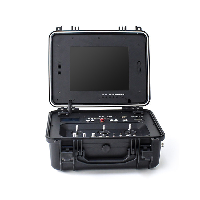
The LKAV-1422 is a COFDM based wireless control station specially designed for UGV/Robotics applications. It integrates video stream receiving and data stream sending/receiving functions, is able to receive and display video/data of the on-board devices, send control commands to the end devices, such as vehicle motion control, PTZ camera control, water cannon control, headlight control, alarm trigger, speed control, emergency stop button, screen selection, etc.
Features
Specification
| Video Frequency | 200-800MHz customizable |
| Video Bandwidth | 2-8MHz adjustable |
| FEC | 1/2, 2/3, 3/4, 5/6, 7/8 |
| Guard Interval | 1/4, 1/8, 1/16, 1/32 |
| Cover Range | 1-3km LOS |
| Data Frequency | 410-500MHz customizable |
| Data Bandwidth | 9600bps |
| Data Output Power | 37dBm |
| Video Output | HDMI (1080p) x1 |
| Video Compression | H.264 |
| RF Connector | N Female x3 |
| Control Method | LED Digital Control Panel |
| Encryption | AES256 |
| Power Input | Battery / DC 12V External Power Supply |
| Working Voltage | DC 12V |
| Working Current | ≤2.5(@12V) |
| Power Consumption | ≤High Power |
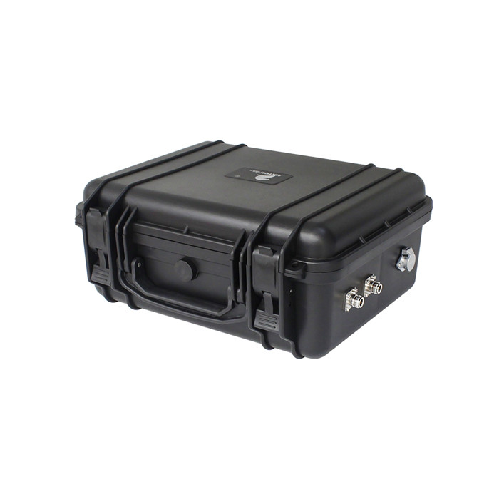
| Dimensions | 425*360*189mm (w/o antenna) |
| Working Temp. | -20℃~+60℃ |
| Weight | 3.8kg (w/o antenna) |
![]()
![]()
![]()
![]()
1. PTZ zoom knob: When rotating clockwise, the pan/tilt lens will zoom out; when rotating counterclockwise, the pan/tilt lens will zoom in.
2. Throttle knob: When it is turned counterclockwise to the end, the data collected at this time corresponds to a value of 0 in the communication protocol. When it is turned clockwise, the value gradually increases. When it is turned to the other end, the value is 250. It is used to indicate the change of the throttle.
3. PTZ enable shift switch: 2nd gear hold switch, dial up, then all related operations of the PTZ are allowed. Dial down, all PTZ related operations are forbidden.
4. Water monitor enable shift switch: 2nd gear holding switch, dial up, then all related operations of water monitor are allowed. Dial down, all water cannon related operations are prohibited.
5. Water cannon blooming DC shift switch: 3-speed self-reset switch, dial upwards, it means that the water cannon is in the form of water curtain; dial down, it means the water cannon is in the form of direct water column.
6. Remote control/manual shift switch: 2nd gear holding switch, dial up means the robot is in remote control mode, dial down means the robot is in manual mode.
7. Illumination shift switch: 2 gear holding switch, dial up to turn on the lighting, dial down to turn off the lighting.
8. Preheating shift switch: 2nd gear holding switch, dial upwards to turn on preheating, dial downwards to turn off preheating.
9. Car body enable shift switch: 2nd gear holding switch, dial up, then all related operations of the car body are allowed. Dial down, all operations related to the car body are prohibited.
10. PTZ joystick: 2D universal joystick, used to operate the PTZ to move up and down, left and right, up and down direction: from bottom to top, the corresponding byte value in the communication protocol changes from 0 to 250, and the left and right direction : From left to right, the corresponding byte value in the communication protocol changes from 0 to 250.
11. Water cannon rocker: 2D universal rocker, used to operate the water cannon up and down, left and right, up and down direction: from bottom to top, the corresponding byte value in the communication protocol changes from 0 to 250, and the left and right direction : From left to right, the corresponding byte value in the communication protocol changes from 0 to 250.
12. Wiper button: self-reset button, click and press to trigger the wiper action in the pan/tilt.
13. System reset button: self-reset button, long press for about 1s to reset the data acquisition and control system of the control box, at the same time the small 4.3-inch data screen is reset, and the code matching stage information is displayed again.
14. Screen cut button: self-reset button, click to switch the 4.3 inch data display small screen display page when pressed.
15. Emergency stop button: self-locking button. When pressed, it means emergency stop operation. At this time, the pan/tilt is enabled, the water cannon is enabled, and the vehicle body is in a forced invalid state. At the same time, the pan/tilt rocker and water cannon are shaken. The corresponding byte value in the left, right, up and down directions of the car body rocker is forced to 125.
16. Small 4.3-inch data display screen: Capacitive touch screen, used to display vehicle end status data, such as engine speed, water temperature and other data. And can also be used to set parameter values, such as: high coolant temperature, etc. You can switch the interface with the cut screen button.
17. Sending indicator light: When data is packaged and sent, this light flashes at 100ms intervals, indicating that the data is being sent.
18. Receiving indicator light: When a data frame is received and the data is parsed correctly, this light flashes.
19. USB: used to store video recording, maximum support 128G. File system---FAT32. The TF card has priority when storing video, and only one of the two storage methods can be selected. After the storage is full, the earliest recorded video will be automatically deleted for loop coverage. (Playing software is best to use perfect decoding)
20. Fault indicator light: When this light flashes at 1s intervals, it means that the image transmission data has not been connected; when it flashes at 2s intervals, it means that the data transmission data has not been connected. When it flashes at 100ms intervals, it means the code value between the remote control terminal and the transmitter. Does not match, need to recharge the code value, when the light is off, it means normal communication.
21. Communication indicator: The indicator light for data transmission. When this light flashes, it means that the data transmission is sending data. When it is not flashing, it means that the data transmission stops sending data.
22. Emergency stop indicator light: When the emergency stop button is pressed, and the emergency stop command is correctly issued to the car terminal, this light is on.
23. Engine indicator light: When the engine speed is not zero, this light is on.
24. Image transmission working status indicator: used to indicate the image transmission working status light, the red light is on to indicate the image transmission is powered on, and the other two green lights flashing indicate that the image transmission is in data transmission.
25. TF-CARD: TF card slot, used for video storage. A TF card can be inserted during storage, the maximum support is 128G, and the file system is FAT32; the TF card storage port has storage priority. After the storage is full, the earliest recorded video will be automatically deleted for loop coverage. (After the device is plugged in the TF card, it will default to recording when it is turned on, and the playback software is best to use perfect decoding)
26. Reserved 1 button: self-reset button, reserved.
27. HDMI external interface: HDMI video expansion port, which can be connected to the display screen, and the output video format is 1080P 60Hz. Consistent with the local display content.
28. FM box: It is used to adjust the receiving frequency of image transmission. Since there is a filter with a fixed center frequency point inside, it is generally not necessary to adjust the frequency of image transmission.
29. Reserved 2 buttons: self-locking button with light, reserved.
30. Coulomb counter: used to display power information.
31. Power switch: self-locking button with light, the green light will be on after pressing, and the whole box board will start to supply power.
32. Water monitor reset button: self-reset button, when pressed, it is used to instruct the water monitor to perform a reset operation.
33. PTZ reset button: self-reset button, after long pressing for 4s, set the current position of the PTZ as the preset position, and after the setting is successful, the PTZ starts to rotate to the right at a constant speed. Click this button, the pan/tilt automatically rotates to the preset position.
34. Car body rocker: 2-dimensional universal rocker, used to operate the car body up and down, left and right, up and down direction: from bottom to top, the corresponding byte value in the communication protocol changes from 0 to 250, and the left and right direction : From left to right, the corresponding byte value in the communication protocol changes from 0 to 250.
35. Car body ignition knob: it is self-locking when it is turned off to power on, and it is self-reset when power on to start. When it is pointed to power on, it means that the car body starts to be powered on. When it is pointed to start, the engine will fire and start.
36. Data transmission suction cup interface: standard N-type female head, used to connect a suction cup or a thin needle to carry the antenna. The data transmission frequency is 490M±10M.
37. Program upgrade port: used to download control system firmware.
38. 12.1 inch high-definition screen: used to display video images. HDMI input.
39. 12V charging port: 3-pin aviation plug, 1 pin 12V positive, 2 pin 12V negative, used in conjunction with the company's power adapter.
40. Video transmission suction cup interface: standard N-type female head, used to connect a suction cup or a thin pin to carry the antenna, and the video transmission frequency is 580M±10M. Please make sure that the antennas are connected before turning on the power.
41. Video transmission suction cup interface: standard N-type female head, used to connect a suction cup or a thin pin to carry the antenna, and the video transmission frequency is 580M±10M. Please make sure that the antennas are connected before turning on the power.
Note: After the remote control box is turned on and powered on, it will first enter the code matching self-check phase. The self-check content includes: check whether the pan/tilt enable switch is turned down, check whether the water monitor enable switch is turned down, and check the car body Whether the enable switch is turned down, check whether the up, down, left, and right values of the gimbal rocker, water monitor rocker, and car body rocker are within the median value, that is, within the range of 100~150, and check whether the throttle knob value is less than 15. After passing the self-inspection, it will enter the code matching stage, which includes: matching the customer code value, matching the code value between the remote control terminal and the transmitting terminal. After the code is passed, the control system enters the normal working state, and the transmitter starts to send control data to the car.


